
Kinematics & Inverse Kinematics · Lesson 08
Denavit–Hartenberg Parameters
Est. 60–80 min
Why
Why this lesson matters
In Lesson 7 you wrote the 6DOF chain by hand: Rz, Tz, Ry, Tx… It worked, but every engineer would write it a little differently. The Denavit–Hartenberg (DH) convention is a standard recipe for placing a frame on each link so that every joint-to-joint step is described by exactly four parameters. Multiply one standard matrix per row and you get forward kinematics. Robot datasheets, textbooks and many solvers speak this language.
By the end of this lesson you will be able to: say what θ, d, a and α each mean in plain words; write the classic DH matrix as Rz(θ)·Tz(d)·Tx(a)·Rx(α); tell which parameter is the variable for a revolute or a prismatic joint; read a DH table and turn it into FK in code; and know that a ‘modified DH’ convention also exists, so you always check which one a table uses.
Concept
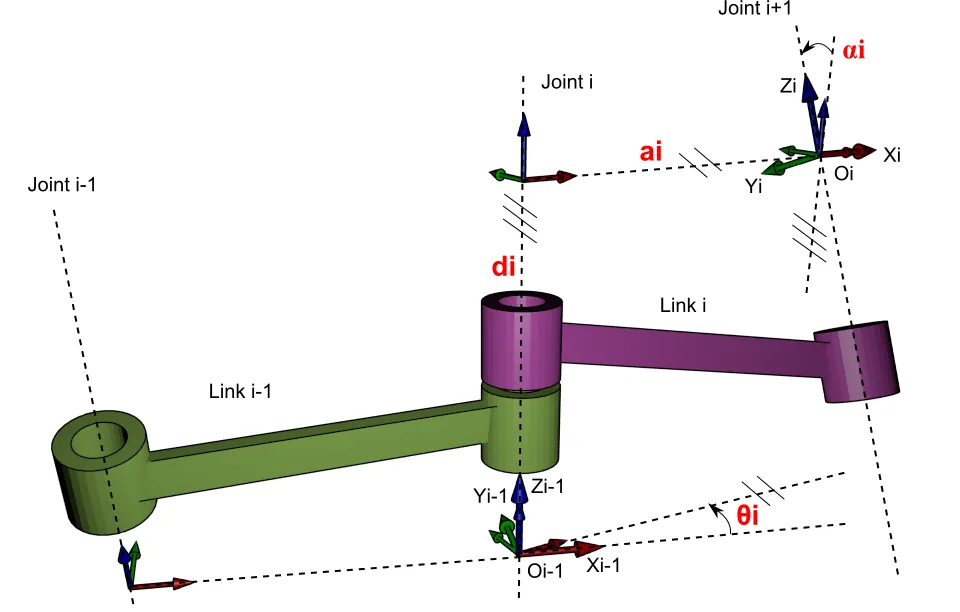
The four DH numbers
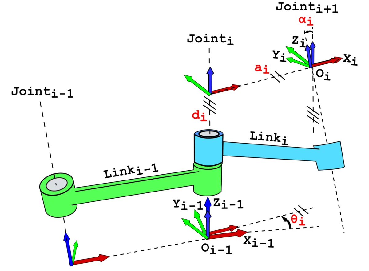
The rule for placing frames (classic DH)
- z axis = joint axis. For a revolute joint, z is the axis the joint turns about; for a sliding (prismatic) joint, z is the direction it slides.
- x axis = common normal. xᵢ is the shortest line that is at right angles to both zᵢ₋₁ and zᵢ, pointing from the old z towards the new one. If the two z axes are parallel there is no unique common normal, and you pick a sensible one.
- y axis = whatever makes it right-handed (Lesson 2’s right-hand rule).
The four parameters, in plain words
| Parameter | Plain meaning | Measured along / about | Revolute joint | Prismatic joint |
|---|---|---|---|---|
| θᵢ (theta) | How much you turn | About the old z axis, from old x to new x | Variable (the joint angle) | Fixed |
| dᵢ | How far you rise or slide | Along the old z axis | Fixed | Variable (the slide) |
| aᵢ (or r) | Link length | Along the new x axis (common normal) | Fixed | Fixed |
| αᵢ (alpha) | Link twist | About the new x axis, from old z to new z | Fixed | Fixed |
One row → one matrix
A_i = Rz(θi) · Tz(di) · Tx(ai) · Rx(αi)

    | cosθ   −sinθ·cosα    sinθ·sinα    a·cosθ |
    | sinθ    cosθ·cosα   −cosθ·sinα    a·sinθ |
    |  0        sinα          cosα          d    |
    |  0         0             0            1    |

FK:  T_0_n = A_1 · A_2 · … · A_n
Look at the matrix: it is the same [R p; 0 1] shape you learnt in Lesson 4. The top-left 3 × 3 is the rotation; the right column is where the new frame’s origin sits. DH does not add any new maths — it is bookkeeping that makes everyone place frames the same way.
Visual
Visualise it: θ is the slider, a is the link
A planar chain is the simplest DH table: one row per link, θᵢ = the slider, aᵢ = the link length, dᵢ = 0, αᵢ = 0.
Interactive · FK chain visualizer (3R planar educational)


Simplified 3R planar stand-in for Base→J1→J2→J3→EE. Full 6DOF adds wrist RPY on top of this position chain.
EE x
153.4
EE y
35.8
ᵇTₑ (planar) calculator
| 0.966 | -0.259 | 0.000 | 157.02 |
| 0.259 | 0.966 | 0.000 | 20.55 |
| 0.000 | 0.000 | 1.000 | 0.00 |
| 0.000 | 0.000 | 0.000 | 1.000 |
Code lab
Code lab: dh.py
dh.py has one function, dh(theta, d, a, alpha), that returns the classic DH matrix. Part 1 changes one parameter at a time so you can *see* what each does. Part 2 writes a planar 2R arm as two rows and checks it against the Lesson 6 formula. Part 3 writes the Lesson 7 example arm as a five-row DH table and checks every pose against the hand-written chain.
# dh.py - Denavit-Hartenberg (classic / distal) parameters in plain Python.
# One DH row (theta, d, a, alpha) -> one 4x4 transform A = Rz(theta) Tz(d) Tx(a) Rx(alpha).
# Multiply the rows in order and you get forward kinematics (Lesson 6-7) in a standard recipe.
# EXAMPLE link sizes in cm, same as fk6.py in Lesson 7 - measure YOUR arm.
import math


def dh(theta, d, a, alpha):
    """Classic DH matrix (Wikipedia 'Denavit-Hartenberg matrix'), angles in degrees."""
    ct, st = math.cos(math.radians(theta)), math.sin(math.radians(theta))
    ca, sa = math.cos(math.radians(alpha)), math.sin(math.radians(alpha))
    return [[ct, -st * ca, st * sa, a * ct],
            [st, ct * ca, -ct * sa, a * st],
            [0, sa, ca, d],
            [0, 0, 0, 1]]


def mul(*Ms):
    out = [[float(i == j) for j in range(4)] for i in range(4)]
    for M in Ms:
        out = [[sum(out[i][k] * M[k][j] for k in range(4)) for j in range(4)] for i in range(4)]
    return out


def pos(T):
    x, y, z = (round(T[i][3], 6) + 0.0 for i in range(3))   # round so -0.00 prints as 0.00
    return f"({x:6.2f}, {y:6.2f}, {z:6.2f})"


# 1) What each parameter does to ONE frame (start at the origin, x forward, z up)
print("1) One DH row, one parameter at a time (cm, degrees)")
for label, row in (("theta=30 (turn about old z)", (30, 0, 0, 0)),
                   ("d=5     (slide along old z)", (0, 5, 0, 0)),
                   ("a=10    (slide along new x)", (0, 0, 10, 0)),
                   ("alpha=90 (twist about new x)", (0, 0, 0, 90))):
    A = dh(*row)
    z_new = f"({A[0][2] + 0.0:5.2f}, {A[1][2] + 0.0:5.2f}, {A[2][2] + 0.0:5.2f})"
    print(f"   {label:<30} origin {pos(A)}  new z axis {z_new}")

# 2) A planar 2R arm: two rows, alpha = 0, d = 0 -> the planar FK from Lesson 6
L1, L2p = 10.0, 8.0
print(f"\n2) Planar 2R arm, a1 = {L1}, a2 = {L2p}")
print("   row | theta | d | a    | alpha")
print(f"    1  | q1    | 0 | {L1:<4} | 0")
print(f"    2  | q2    | 0 | {L2p:<4} | 0")
for q1, q2 in ((0, 0), (90, 0), (30, 60), (45, -90)):
    T = mul(dh(q1, 0, L1, 0), dh(q2, 0, L2p, 0))
    x = L1 * math.cos(math.radians(q1)) + L2p * math.cos(math.radians(q1 + q2))
    y = L1 * math.sin(math.radians(q1)) + L2p * math.sin(math.radians(q1 + q2))
    print(f"   q = ({q1:3}, {q2:3}) -> DH tip {pos(T)}   planar formula ({x:6.2f}, {y:6.2f})")

# 3) The Lesson 7 example arm as a 5-row DH table
D1, L2, L3, L4 = 9.0, 10.5, 9.8, 14.0
TABLE = [  # (theta offset, d, a, alpha) ; theta_i = q_i + offset
    (0, D1, 0, 90),     # J1 base yaw: rise to the shoulder, twist so z1 = shoulder axis
    (0, 0, L2, 0),      # J2 shoulder pitch: upper arm
    (0, 0, L3, 0),      # J3 elbow pitch: forearm
    (90, 0, 0, 90),     # J4 wrist pitch: offset 90 deg + twist so z4 = gripper axis
    (0, L4, 0, 0),      # J5 wrist roll: out along the gripper to the tip
]


def fk_dh(q):
    As = [dh(qi + off, d, a, al) for qi, (off, d, a, al) in zip(q, TABLE)]
    return mul(*As[:3]), mul(*As)


def fk_lesson7(q):  # the hand-written chain from fk6.py (Lesson 7), positions only
    j1, j2, j3, j4, _ = (math.radians(v) for v in q)
    r_w = L2 * math.cos(j2) + L3 * math.cos(j2 + j3)
    z_w = D1 + L2 * math.sin(j2) + L3 * math.sin(j2 + j3)
    r = r_w + L4 * math.cos(j2 + j3 + j4)
    z = z_w + L4 * math.sin(j2 + j3 + j4)
    return (r * math.cos(j1), r * math.sin(j1), z)


print("\n3) Example arm DH table (cm, deg)   theta_i = q_i + offset")
print("   row | offset | d    | a    | alpha")
for i, (off, d, a, al) in enumerate(TABLE, 1):
    print(f"    {i}  | {off:>6} | {d:<4} | {a:<4} | {al}")
print(f"\n   {'J1..J5 (deg)':<24} {'DH wrist':>24} {'DH tip':>24}  matches Lesson 7?")
worst = 0.0
for q in ((0, 0, 0, 0, 0), (0, 90, 0, 0, 0), (0, 45, -45, -45, 0), (90, 45, -45, -45, 0),
          (30, 70, -80, -80, 0), (30, 70, -80, -80, 90)):
    Tw, Tt = fk_dh(q)
    ref = fk_lesson7(q)
    err = max(abs(Tt[i][3] - ref[i]) for i in range(3))
    worst = max(worst, err)
    print(f"   {str(q):<24} {pos(Tw):>24} {pos(Tt):>24}  {'yes' if err < 1e-9 else 'NO'}")

print("\nWhat to notice")
print(f"- worst difference between DH chain and Lesson 7 chain: {worst:.1e} cm (same arm, two bookkeeping styles)")
print("- revolute joints: only theta changes; d, a, alpha are fixed numbers you measure once")
print("- the 90 deg offset on row 4 is part of the model: forget it and every pose is wrong")
Output (run with python3 dh.py)
1) One DH row, one parameter at a time (cm, degrees)
   theta=30 (turn about old z)    origin (  0.00,   0.00,   0.00)  new z axis ( 0.00,  0.00,  1.00)
   d=5     (slide along old z)    origin (  0.00,   0.00,   5.00)  new z axis ( 0.00,  0.00,  1.00)
   a=10    (slide along new x)    origin ( 10.00,   0.00,   0.00)  new z axis ( 0.00,  0.00,  1.00)
   alpha=90 (twist about new x)   origin (  0.00,   0.00,   0.00)  new z axis ( 0.00, -1.00,  0.00)

2) Planar 2R arm, a1 = 10.0, a2 = 8.0
   row | theta | d | a    | alpha
    1  | q1    | 0 | 10.0 | 0
    2  | q2    | 0 | 8.0  | 0
   q = (  0,   0) -> DH tip ( 18.00,   0.00,   0.00)   planar formula ( 18.00,   0.00)
   q = ( 90,   0) -> DH tip (  0.00,  18.00,   0.00)   planar formula (  0.00,  18.00)
   q = ( 30,  60) -> DH tip (  8.66,  13.00,   0.00)   planar formula (  8.66,  13.00)
   q = ( 45, -90) -> DH tip ( 12.73,   1.41,   0.00)   planar formula ( 12.73,   1.41)

3) Example arm DH table (cm, deg)   theta_i = q_i + offset
   row | offset | d    | a    | alpha
    1  |      0 | 9.0  | 0    | 90
    2  |      0 | 0    | 10.5 | 0
    3  |      0 | 0    | 9.8  | 0
    4  |     90 | 0    | 0    | 90
    5  |      0 | 14.0 | 0    | 0

   J1..J5 (deg)                             DH wrist                   DH tip  matches Lesson 7?
   (0, 0, 0, 0, 0)          ( 20.30,   0.00,   9.00) ( 34.30,   0.00,   9.00)  yes
   (0, 90, 0, 0, 0)         (  0.00,   0.00,  29.30) (  0.00,   0.00,  43.30)  yes
   (0, 45, -45, -45, 0)     ( 17.22,   0.00,  16.42) ( 27.12,   0.00,   6.53)  yes
   (90, 45, -45, -45, 0)    (  0.00,  17.22,  16.42) (  0.00,  27.12,   6.53)  yes
   (30, 70, -80, -80, 0)    ( 11.47,   6.62,  17.17) ( 11.47,   6.62,   3.17)  yes
   (30, 70, -80, -80, 90)   ( 11.47,   6.62,  17.17) ( 11.47,   6.62,   3.17)  yes

What to notice
- worst difference between DH chain and Lesson 7 chain: 3.6e-15 cm (same arm, two bookkeeping styles)
- revolute joints: only theta changes; d, a, alpha are fixed numbers you measure once
- the 90 deg offset on row 4 is part of the model: forget it and every pose is wrongTry it: each slider is a θᵢ; the fixed link lengths are the aᵢ column (planar, so every α and d is 0). Write the 3-row table for what you see.
Interactive · FK chain visualizer (3R planar educational)
Simplified 3R planar stand-in for Base→J1→J2→J3→EE. Full 6DOF adds wrist RPY on top of this position chain.
EE x
153.4
EE y
35.8
ᵇTₑ (planar) calculator
| 0.966 | -0.259 | 0.000 | 157.02 |
| 0.259 | 0.966 | 0.000 | 20.55 |
| 0.000 | 0.000 | 1.000 | 0.00 |
| 0.000 | 0.000 | 0.000 | 1.000 |
Real world
DH in the real world
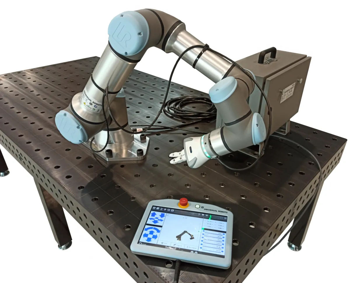
- Robot makers publish DH tables for their arms so users can compute FK and IK in their own software. Universal Robots, for example, publishes DH parameters for its cobots on its support site.
- Textbooks and courses teach DH as a standard way to write FK; *Modern Robotics* gives it its own appendix (Appendix C).
- Software: many robotics toolboxes let you build a robot directly from a DH table; ROS uses URDF files, which give each joint’s origin and axis — a close cousin of DH (Lesson 9).
- History: Denavit and Hartenberg introduced the convention in 1955 for spatial linkages; Richard Paul’s 1981 book showed how useful it is for robot arms.
Bench build
Bench build: a cardboard teach arm that prints its DH table
Make a two-link arm from stiff cardboard or ice-cream sticks: link 1 is 10 cm, link 2 is 8 cm (shaft centre to shaft centre). Use two 10 kΩ potentiometers as the joints — the pot shaft is the joint axis, so its z axis points out of the table. Turn the links by hand; the Arduino reads θ₁ and θ₂, builds the two DH matrices and prints the tip. No motors, so it is safe on USB power.
Wire the pots
Each pot: outer legs to 5V and GND, middle leg (wiper) to A0 (joint 1) or A1 (joint 2).
Mark zero
Lay both links straight along a pencil line (the base x axis). Open Serial Monitor, note each raw reading and put it in RAW_ZERO.
Check the scale
Most small pots turn about 270°, but check your pot’s datasheet and change DEG_PER_COUNT if needed.
Compare
Put the links at (30°, 60°) with a protractor. The sketch should print a tip close to (8.66, 13.00) cm — same as
dh.py. Measure with a ruler from the joint 1 shaft.
// dh_teach_2r.ino - a cardboard 2R "teach arm" that prints its own DH table and tip position.
// Two 10 kOhm potentiometers are the joints: turn them by hand, the Arduino reads theta1 and
// theta2, builds the two classic DH matrices A = Rz(theta) Tz(d) Tx(a) Rx(alpha) and multiplies them.
// Same maths as dh.py part 2. This sketch drives NO motor or servo - pots only, so it is safe
// to power from USB. (If you later add servos: separate 5-6 V supply, common ground, never the 5 V pin.)
//
// Wiring: each pot: outer legs to 5V and GND, middle leg (wiper) to A0 (joint 1) / A1 (joint 2).
// Calibrate: set each link straight along the base x line and note the reading -> RAW_ZERO.

const float A1_LEN = 10.0, A2_LEN = 8.0;          // cm, shaft centre to shaft centre - MEASURE
const int RAW_ZERO[2] = {512, 512};              // pot reading when the joint is at 0 deg
const float DEG_PER_COUNT = 270.0 / 1023.0;      // typical 270 deg pot - check your pot's datasheet

// one DH row (theta, d, a, alpha) -> 4x4 matrix
void dhRow(float th, float d, float a, float al, float M[4][4]) {
  float ct = cos(radians(th)), st = sin(radians(th));
  float ca = cos(radians(al)), sa = sin(radians(al));
  float R[4][4] = {{ct, -st * ca, st * sa, a * ct},
                   {st, ct * ca, -ct * sa, a * st},
                   {0, sa, ca, d},
                   {0, 0, 0, 1}};
  memcpy(M, R, sizeof(R));
}

void mul4(float A[4][4], float B[4][4], float C[4][4]) {
  for (int i = 0; i < 4; i++)
    for (int j = 0; j < 4; j++) {
      C[i][j] = 0;
      for (int k = 0; k < 4; k++) C[i][j] += A[i][k] * B[k][j];
    }
}

void setup() {
  Serial.begin(115200);
  Serial.println(F("row | theta | d | a    | alpha"));
  Serial.println(F(" 1  | q1    | 0 | 10.0 | 0"));
  Serial.println(F(" 2  | q2    | 0 | 8.0  | 0"));
}

void loop() {
  float q1 = (analogRead(A0) - RAW_ZERO[0]) * DEG_PER_COUNT;
  float q2 = (analogRead(A1) - RAW_ZERO[1]) * DEG_PER_COUNT;
  float A1m[4][4], A2m[4][4], T[4][4];
  dhRow(q1, 0, A1_LEN, 0, A1m);
  dhRow(q2, 0, A2_LEN, 0, A2m);
  mul4(A1m, A2m, T);
  Serial.print(F("q1 ")); Serial.print(q1, 1);
  Serial.print(F("  q2 ")); Serial.print(q2, 1);
  Serial.print(F("  ->  tip x ")); Serial.print(T[0][3], 2);
  Serial.print(F("  y ")); Serial.print(T[1][3], 2);
  Serial.print(F("  tool heading ")); Serial.print(degrees(atan2(T[1][0], T[0][0])), 1);
  Serial.println(F(" deg"));
  delay(300);
}
Debugging
Debugging a DH model
| Symptom | Likely cause | Fix |
|---|---|---|
| Everything off by 90° at one joint | Missing θ offset | Add the offset: θᵢ = qᵢ + offset |
| Arm folds the wrong way in 3D | Wrong sign on an α (±90°) | Redraw the z axes and check the right-hand rule |
| Numbers match a book only sometimes | Book uses modified DH, you use classic (or the reverse) | Write the convention at the top; convert, don’t mix |
| Tip height wrong by a constant | A d value is wrong (e.g. base height) | Re-measure along the joint axis |
| Error grows with reach | An a value or a joint zero is slightly off | Re-measure shaft centre to shaft centre; re-zero |
| Your matrix is not a valid rotation | Degrees passed to cos/sin as radians | Convert with math.radians / radians() |
Think
Think about it
Think
Arjun says, “A DH table has four columns, so each joint has four motors.” What is wrong with that?
Experiment
Try it in the lab
About 45 minutes with dh.py, paper and a pencil, and optionally the cardboard teach arm.
Experiment
Write and test your first DH tables
You will need
- `dh.py` and Python 3
- Paper, pencil, protractor
- Optional: Arduino UNO, two 10 kΩ pots, cardboard links for `dh_teach_2r.ino`
Steps
- Run `dh.py`. In Part 1, change α to −90° and predict the new z axis before running again.
- Add a third row to the planar 2R table (a₃ = 5 cm). Check (0, 0, 0) gives a tip at 23 cm.
- In Part 3, set the row 4 offset to 0 and run. Write down how wrong the tip becomes for (30, 70, −80, −80, 0).
- Draw the five frames of the example arm on paper (side view), marking every z and x axis.
- If you built the teach arm, compare three poses with the printed tip and a ruler.
- In the visualiser, set three angles and write the matching 3-row DH table.
Interactive · FK chain visualizer (3R planar educational)
Simplified 3R planar stand-in for Base→J1→J2→J3→EE. Full 6DOF adds wrist RPY on top of this position chain.
EE x
153.4
EE y
35.8
ᵇTₑ (planar) calculator
| 0.966 | -0.259 | 0.000 | 157.02 |
| 0.259 | 0.966 | 0.000 | 20.55 |
| 0.000 | 0.000 | 1.000 | 0.00 |
| 0.000 | 0.000 | 0.000 | 1.000 |
Every row turns into the same kind of matrix, and multiplying them gives exactly the FK you wrote by hand. The table is shorter to share and harder to misread — as long as you follow one convention.
Knowledge check
Check your understanding
Knowledge check
1. How many parameters does each row of a classic DH table have?
2. For a revolute joint, which DH parameter is the variable?
3. In classic DH, the z axis of a frame is placed…
4. What does α (link twist) describe?
5. For a planar arm where all joints turn about parallel axes, α and d are…
6. A book’s DH table for your robot looks different from yours, but both give correct FK. Most likely…
7. The classic DH matrix for one row equals…
Mini assignment
Hands-on assignment
Mini assignment
DH reference card
Make a one-page DH reference card you can keep next to your bench.
Deliverables
- The four parameters with one-line plain meanings and a small sketch each.
- The classic DH matrix written out, and the order Rz·Tz·Tx·Rx.
- The planar 2R table and the example-arm table from `dh.py`, labelled ‘classic DH’.
- Your result from the ‘offset = 0’ experiment: how far off the tip was.
- One sentence on how modified DH differs.
Do this, step by step
- Run
python3 dh.pyand check that the DH chain and the hand-written Lesson 7 chain give the same tip. - For the planar 2R table, compute the tip at (90°, −90°) by hand with the DH matrix, and compare with the code.
- Set the 90° offset on row 4 to 0, run again and write down how far the tip moved. Put it back afterwards.
- Write the four parameters (θ, d, a, α) on your card with one plain sentence and a small sketch each.
- Optional bench: build the two-pot DH teach arm, move it to three grid points and compare the printed tip with a ruler.
Stuck? Hints, one at a time
- Classic DH order is Rz(θ) · Tz(d) · Tx(a) · Rx(α).
- a and α describe the link (fixed numbers); θ is the joint variable for a revolute joint.
- Modified DH puts the link parameters before the joint, so the same arm gets a different-looking table.
Challenges (pick by level)
- 🟢 Easy: By hand, find the tip of the 2R arm at (90°, −90°) and check with
dh.py. - 🟢 Easy: For a prismatic joint (like a 3D-printer Z axis), say which parameter changes.
- 🟡 Medium: Add a function
dh_modified(alpha_prev, a_prev, theta, d)and show it gives the same 2R tip with its own table. - 🟠 Hard-ish: Write the DH table for a SCARA arm (two revolute joints with vertical axes, then a vertical slide).
- 🔴 Hard: Prove from the matrix that rotating θ and translating d about the same z axis can be done in either order.
- ⚫ Research: Find the published DH table for one real cobot and say whether it is classic or modified.
Next step
You can now read a DH table. In Lesson 9 — Building a DH Table you will build one yourself, step by step, for a real arm and validate it before trusting it.
Look back: Lesson 7: Forward Kinematics — 6DOF Arm. Next: Lesson 9: Building a DH Table. Related: Stage 1: Homogeneous Transformation and Stage 10 — ROS 2.
Sources
- Wikipedia — Denavit–Hartenberg parameters — 1955 origin, frame rules (z = joint axis, x = common normal), the four parameters, the classic DH matrix, and modified DH.
- Modern Robotics — K. M. Lynch & F. C. Park (book home page, free preprint) — Forward Kinematics chapter, including an appendix on DH parameters.
- Universal Robots — DH parameters for calculations of kinematics and dynamics — a manufacturer’s published DH tables.
- Lesson 7 of this stage — the example arm (D1 = 9, L2 = 10.5, L3 = 9.8, L4 = 14 cm) checked against the DH table.
- Photos: Wikimedia Commons (credits under each image).
Self-attested for now — keep artifacts in your lab notebook.
Complete
Today's goal
0 of 1 done today
Mark this lesson complete when you have worked the experiment, knowledge check, and assignment (even roughly).