
Kinematics & Inverse Kinematics · Lesson 02
Coordinate Frames & Reference Frames
Est. 45–60 min
Why
Why this lesson matters
In Lesson 1 you said “the tip is at (12, 6)”. But (12, 6) measured from where, and along which directions? A position only means something when you name its frame. A robot has many frames — the base, every link, the tool, the camera, the table — and kinematics is mostly about moving numbers correctly from one frame to another.
By the end of this lesson you will be able to: say what a coordinate frame is (an origin plus axes); use the right-hand rule to check a 3D frame; name the common robot frames (world, base, link, flange, tool, camera, sensor); convert a point from one frame to another with p_B = R·p_A + o; and turn a real distance-sensor reading into a point in the robot’s base frame.
Concept
What a frame is
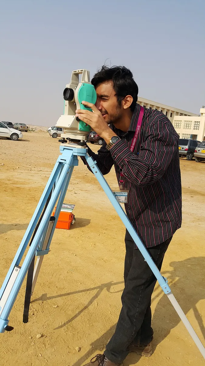
A frame = an origin + axes
A coordinate frame is a point called the origin plus a set of axes: x and y on a flat table, or x, y and z in 3D. The axes are at right angles to each other and have a unit length. Any point can then be written as numbers along those axes. Change the origin or turn the axes, and the *same* point gets *different* numbers.
We name frames with curly brackets: {B} for the robot base, {C} for a camera, {T} for the tool. We also write the frame as a subscript: p_B means “point p, written in frame {B}”. Never write x, y, z without saying which frame — that is the most common mistake in robotics notebooks.
Right-handed frames
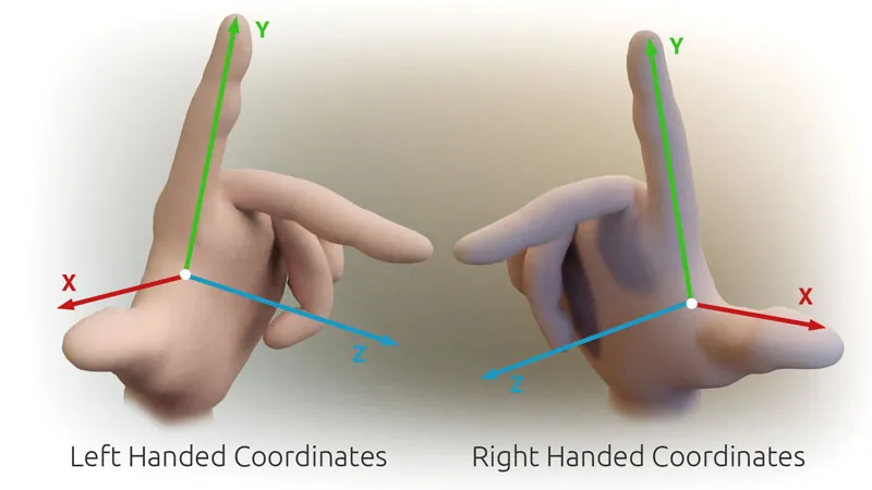
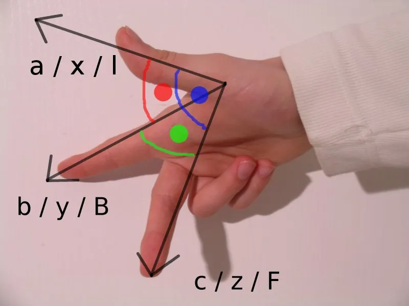
In 3D there are two ways to arrange three axes, and they are mirror images. Robotics (and ROS) uses right-handed frames: curl the fingers of your right hand from +x towards +y and your thumb points along +z. Or: thumb = x, index finger = y, middle finger = z. ROS also suggests a habit for bodies like a mobile robot or a camera mount: x forward, y left, z up.
The frames on a robot arm
| Frame | Where its origin is | Used for |
|---|---|---|
| World {W} | A fixed point in the room or on the table | Where everything is, shared by all robots and cameras |
| Base {B} | The bottom of the robot, on the first joint axis | The robot’s own ‘home’ frame; FK usually gives the tool in {B} |
| Link / joint {1}, {2}, … | On each joint axis | Building FK one link at a time (Lessons 6–9) |
| Flange {F} | The mounting plate at the end of the last link | Where tools are bolted on |
| Tool {T} | The working point: pen tip, gripper centre, weld tip | What the task cares about |
| Camera {C} / sensor {S} | Inside the camera or sensor | Where measurements are first written |
Moving a point between frames (2D)
Suppose frame {A} sits inside frame {B}: its origin is at o (measured in {B}) and it is turned by an angle yaw. A point written in {A} as p_A becomes, in {B}:
p_B = R(yaw) · p_A + o

R(yaw) = [ cos(yaw)  −sin(yaw) ]
         [ sin(yaw)   cos(yaw) ]
Read it in two steps: first rotate the point by yaw so its numbers line up with {B}’s axes, then add the origin o to slide it into place. To go back from {B} to {A}, do the opposite in the opposite order: subtract o, then rotate by −yaw. In Lessons 4–5 you will pack R and o into one matrix.
Visual
Visualise it: the frame explorer
Drag and turn the tool frame. The point does not move — only its numbers in each frame change.
Interactive · Coordinate-frame explorer

Code lab
Code lab: one cup, three frames
frames.py has a camera {C} on the table, 30 cm in front of the robot base and 10 cm to its left, turned 180° so it looks back at the robot. The camera sees a cup. The code converts the cup into the base frame, converts it back, shows how far the arm would miss if you forgot the frame, and finally finds the pen tip {T} from the flange {F}.
# frames.py - one cup, three frames, three different sets of numbers (top view, 2D, cm).
# A frame = an origin + x and y axes. To move a point from frame {A} into frame {B}:
#     p_B = R(yaw) * p_A + o      (o = where A's origin is, measured in B; yaw = how A is turned)
import math


def rot(yaw_deg):
    c, s = math.cos(math.radians(yaw_deg)), math.sin(math.radians(yaw_deg))
    return ((c, -s), (s, c))


def a_to_b(p, yaw_deg, origin):
    """Point p given in frame A -> the same point in frame B."""
    (r00, r01), (r10, r11) = rot(yaw_deg)
    return (r00 * p[0] + r01 * p[1] + origin[0], r10 * p[0] + r11 * p[1] + origin[1])


def b_to_a(p, yaw_deg, origin):
    """The reverse: subtract the origin, then rotate back by -yaw."""
    q = (p[0] - origin[0], p[1] - origin[1])
    return a_to_b(q, -yaw_deg, (0.0, 0.0))


# Frame {C}: a camera on the table, 30 cm in front of the robot base {B} and 10 cm to the left,
# turned 180 deg so it looks back at the robot.
CAM_YAW, CAM_ORIGIN = 180.0, (30.0, 10.0)
# Frame {T}: the tool (pen tip) on the arm's flange {F}: 5 cm further along the flange's x axis.
TOOL_IN_FLANGE = (5.0, 0.0)

cup_in_cam = (12.0, 4.0)                    # what the camera reports
cup_in_base = a_to_b(cup_in_cam, CAM_YAW, CAM_ORIGIN)
print("1) The same cup in two frames")
print(f"   camera {{C}} says: x = {cup_in_cam[0]:6.2f}, y = {cup_in_cam[1]:6.2f}")
print(f"   base   {{B}} says: x = {cup_in_base[0]:6.2f}, y = {cup_in_base[1]:6.2f}")
back = b_to_a(cup_in_base, CAM_YAW, CAM_ORIGIN)
print(f"   and back to {{C}}: x = {back[0]:6.2f}, y = {back[1]:6.2f}   (round trip works)")

print("\n2) Forgetting the frame: using the camera numbers as if they were base numbers")
err = math.dist(cup_in_cam, cup_in_base)
print(f"   the arm would miss the cup by {err:.2f} cm")

print("\n3) Flange {F} vs tool {T}: where is the pen tip?")
for flange_yaw, flange_origin in ((0.0, (18.0, 0.0)), (90.0, (0.0, 18.0)), (45.0, (12.73, 12.73))):
    tip = a_to_b(TOOL_IN_FLANGE, flange_yaw, flange_origin)
    print(f"   flange at ({flange_origin[0]:5.2f}, {flange_origin[1]:5.2f}) yaw {flange_yaw:4.0f}°"
          f" -> pen tip at ({tip[0]:5.2f}, {tip[1]:5.2f})")
Output (run with python3 frames.py)
1) The same cup in two frames
   camera {C} says: x =  12.00, y =   4.00
   base   {B} says: x =  18.00, y =   6.00
   and back to {C}: x =  12.00, y =   4.00   (round trip works)

2) Forgetting the frame: using the camera numbers as if they were base numbers
   the arm would miss the cup by 6.32 cm

3) Flange {F} vs tool {T}: where is the pen tip?
   flange at (18.00,  0.00) yaw    0° -> pen tip at (23.00,  0.00)
   flange at ( 0.00, 18.00) yaw   90° -> pen tip at ( 0.00, 23.00)
flange at (12.73, 12.73) yaw 45° -> pen tip at (16.27, 16.27)Try it: move and turn the tool frame and watch the same point get new numbers in the base frame.
Interactive · Coordinate-frame explorer
Real world
Frames in the real world
- Robot cells: a vision camera reports parts in its own frame; a one-time calibration finds the camera’s pose in the robot base frame so every part can be converted.
- ROS: every robot is a tree of named frames (base_link, tool0, camera_link…) and a library called tf2 converts points between them. ROS frames are right-handed, with x forward, y left, z up for bodies.
- Surveying and maps: land surveyors and GPS all measure against agreed reference frames so maps from different teams fit together.
- Tool changes: when a robot swaps a gripper for a screwdriver, only the flange-to-tool offset changes — the rest of the kinematics stays the same.
Bench build
Bench build: a sensor that reports in the robot’s frame
An HC-SR04 ultrasonic sensor measures distance straight ahead, so in its own frame {S} an object is always at (d, 0). Place the sensor on the table at a measured position and angle in the robot base frame {B}, and sensor_to_base.ino prints the object in {B} — numbers the arm could use directly.
| HC-SR04 pin | Arduino | Note |
|---|---|---|
| VCC | 5 V | The sensor needs 5 V |
| GND | GND | — |
| TRIG | Pin 9 | Arduino sends a 10 µs pulse |
| ECHO | Pin 10 | Sensor answers with a pulse as long as the echo time |
Draw the base frame
Tape a sheet of chart paper on the table. Mark the base origin and draw +x (forward) and +y (left) with a ruler.
Place the sensor
Put the sensor at, say, x = 25 cm, y = −10 cm, facing +y (yaw 90°). Type those numbers into
SENSOR_X,SENSOR_YandSENSOR_YAW_DEG.Upload and read
Open Serial Monitor at 115200. Put a box in front of the sensor and note x_B, y_B.
Check with a ruler
Measure the box’s front face from the base origin. It should agree within about 1 cm.
Break it on purpose
Turn the sensor 30° without changing
SENSOR_YAW_DEG. How wrong do the numbers get? Now fix the yaw in the code.
// sensor_to_base.ino - turn a distance-sensor reading into a point in the ROBOT BASE frame.
// An HC-SR04 ultrasonic sensor sits on the table at a known place and angle (its own frame {S}).
// It measures distance d straight ahead (along its x axis), so in {S} the object is at (d, 0).
// Then p_B = R(yaw) * p_S + o  gives the object in the base frame {B} - the frame the arm uses.
// Wiring: VCC -> 5 V, GND -> GND, TRIG -> pin 9, ECHO -> pin 10. No motors in this build.
const int TRIG = 9, ECHO = 10;
// Where the sensor is, measured in the BASE frame with a ruler (cm, degrees). CHANGE THESE.
const float SENSOR_X = 25.0, SENSOR_Y = -10.0, SENSOR_YAW_DEG = 90.0;

float readCm() {
  digitalWrite(TRIG, LOW); delayMicroseconds(2);
  digitalWrite(TRIG, HIGH); delayMicroseconds(10);
  digitalWrite(TRIG, LOW);
  unsigned long us = pulseIn(ECHO, HIGH, 30000UL);   // time-out after 30 ms (about 5 m)
  if (us == 0) return -1;                           // nothing in range
  return us * 0.0343 / 2.0;                         // speed of sound ~343 m/s, there and back
}

void setup() {
  pinMode(TRIG, OUTPUT); pinMode(ECHO, INPUT);
  Serial.begin(115200);
  Serial.println(F("d_cm,  x_S, y_S,  ->  x_B, y_B"));
}

void loop() {
  float d = readCm();
  if (d < 0) { Serial.println(F("no echo")); delay(300); return; }
  float xs = d, ys = 0;                             // the point in the SENSOR frame
  float a = radians(SENSOR_YAW_DEG);
  float xb = cos(a) * xs - sin(a) * ys + SENSOR_X;  // rotate, then add the sensor's origin
  float yb = sin(a) * xs + cos(a) * ys + SENSOR_Y;
  Serial.print(d, 1); Serial.print(F(",  ")); Serial.print(xs, 1); Serial.print(F(", "));
  Serial.print(ys, 1); Serial.print(F(",  ->  ")); Serial.print(xb, 1); Serial.print(F(", "));
  Serial.println(yb, 1);
  delay(300);
}Debugging
Debugging frames
| Symptom | Likely cause | Fix |
|---|---|---|
| Point is mirrored left–right | One axis points the wrong way (left-handed frame) | Check with the right-hand rule; flip that axis |
| Error grows the further the object is | Yaw is wrong | Measure the sensor or camera angle again |
| Error is the same everywhere | Origin o is wrong | Re-measure where the frame’s origin is |
| Round trip does not give the start point back | Inverse done in the wrong order | Subtract o first, then rotate by −yaw |
| Numbers look right but the arm misses | Mixed tool frame and flange frame | Add the tool offset (code Part 3) |
Think
Think about it
Think
A camera is bolted to the robot’s wrist instead of the table. The arm moves. Do the numbers you need to convert camera points into the base frame stay the same?
Experiment
Try it in the lab
About 30 minutes with the Python file, the frame explorer and (optionally) the sensor bench.
Experiment
Frames on your desk
You will need
- `frames.py` and Python 3
- Frame explorer (in your browser)
- Chart paper, ruler, protractor
- Optional: Arduino UNO, HC-SR04 sensor, jumper wires, a small box
Steps
- Hold up your right hand and make a right-handed frame. Point x at the door — where does z point?
- Run `frames.py`. Check the cup’s base-frame numbers by hand: rotate (12, 4) by 180°, then add (30, 10).
- Change `CAM_YAW` to 90° and predict the new base-frame position before running.
- Add a second camera on the other side of the table and convert the same cup from it. Do both cameras agree in {B}?
- In the frame explorer, find a tool pose where the point’s tool-frame numbers are (0, 0).
- Optional: build the sensor bench and check three box positions with a ruler.
Interactive · Coordinate-frame explorer
A wrong origin shifts every point by the same amount; a wrong yaw makes the error grow with distance. Both give believable numbers, which is why you must always name and check your frames.
Knowledge check
Check your understanding
Knowledge check
1. A coordinate frame is made of…
2. p_B = R·p_A + o converts a point…
3. In a right-handed frame, curling your right fingers from +x to +y makes your thumb point along…
4. In frames.py the camera says (12, 4) and the base says (18, 6). How far would the arm miss if you used the camera numbers directly?
5. Your converted points are wrong by more when the object is farther away. The most likely cause is…
6. The tool frame {T} is different from the flange frame {F} when…
7. ROS’s habit for a body frame is…
Mini assignment
Hands-on assignment
Mini assignment
Frame map of your robot desk
Draw every frame on your robot desk and convert one object through them.
Deliverables
- A top-view sketch with {W}, {B}, {F}, {T} and one sensor or camera frame, each with origin and x, y axes (and z by the right-hand rule).
- A table listing each frame’s origin and yaw measured in {B}.
- One object converted from the sensor/camera frame into {B} by hand, and checked with `frames.py`.
- One sentence each: what goes wrong with a wrong origin, and with a wrong yaw.
- Optional: three sensor-bench readings next to ruler measurements.
Do this, step by step
- Run
python3 frames.py. Check Part 1 by hand: rotate the camera point by the camera’s yaw, then add the camera origin. - Measure your own desk: put a sheet of graph paper down as {B} and mark where {W}, the flange {F}, the tool {T} and one sensor sit. Write each origin and yaw in a table.
- Pick one object (a coin or eraser). Measure it in the sensor frame with a ruler, convert it to {B} by hand, then change the numbers in
frames.pyand confirm. - On purpose, use a wrong yaw (add 10°) and then a wrong origin (add 2 cm). Write down how far the converted point moves each time.
- In the frame explorer, set the same yaw and origin as your sensor and check the drawn point matches your table.
Stuck? Hints, one at a time
- Rotate first, then add the origin. Doing it the other way round moves the point wrongly.
- Yaw is measured from the {B} x axis, anticlockwise positive when seen from above (z up).
- If the round trip does not return the same point, check the sign of the yaw in
b_to_a().
Challenges (pick by level)
- 🟢 Easy: Use your right hand to label z for three different x, y pairs drawn by a friend.
- 🟢 Easy: Convert (10, 0) from a frame with yaw 90° and origin (5, 5) into {B} by hand.
- 🟡 Medium: Add a second camera to
frames.pyand show both cameras give the same base-frame cup. - 🟠 Hard-ish: Write
chain(p, frames)that converts a point through a list of (yaw, origin) frames, e.g. tool → flange → base. - 🔴 Hard: Extend
frames.pyto 3D with a rotation about z only, and check your frame with the right-hand rule. - ⚫ Research: Read ROS REP 103 and list the three conventions it sets for body frames and camera (optical) frames.
Next step
A frame tells you *where from*. In Lesson 3 — Position, Orientation & Pose you will describe both *where* the tool is and *which way it points* — together called its pose.
Look back: Lesson 1: Why Robots Need Kinematics. Next: Lesson 3: Position, Orientation & Pose. Related: Stage 1: Frames & Reference Frames and Stage 11 — Computer Vision.
Sources
- ROS REP 103 — Standard Units of Measure and Coordinate Conventions (source text) — all ROS frames are right-handed; body frames use x forward, y left, z up.
- Wikipedia — Right-hand rule — right- vs left-handed axes; right-handed coordinate systems are used in rigid-body kinematics.
- Wikipedia — Robot kinematics — links as rigid bodies joined by revolute or prismatic joints.
- Photos and diagram: Wikimedia Commons (credits under each image).
Self-attested for now — keep artifacts in your lab notebook.
Complete
Today's goal
0 of 1 done today
Mark this lesson complete when you have worked the experiment, knowledge check, and assignment (even roughly).